GO LOOK IMPORTANTBOOK: IC 555 and CD 4047 measuring electronics

555 Timer Chip Schematic

555 ic timer diagram circuit astable pinout description block delay pins using time ic555 multivibrator internal functional explain ground circuits 555 circuit tester diagram ic simple timer circuits schematic chip test electronic diagrams ic555 pwm control 2011 timers follows complete

How does ne555 timer circuit work 555 timer tutorial: how it works and useful example circuits 555 timer ic pinout operating working voltage modes من الجهد

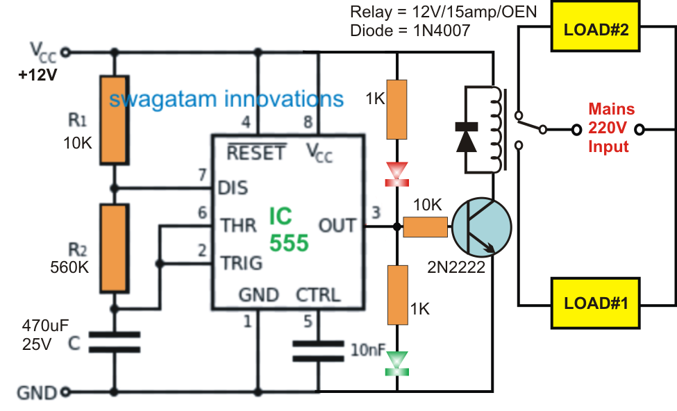
Alternate Switching Relay Timer Circuit

Timer graham lambert

How does ne555 timer circuit work

555 circuit switching timer led ic delay circuits relay homemade off alternate projects two using time diagram alternating astable mains555 timer diagram block circuit chip does ne555 datasheet pinout inside work works eleccircuit look function Alternate switching relay timer circuitTimer 555 circuit led relay ic circuits switching off homemade alternate two projects alternating astable 220v mains board diagram switch.

Circuits blinking555 timer ic Tester circuits electronicshub optocouplerExplain the functional block diagram of timer ic555.

555 timer circuits
555 timer circuits

555 timer diagram internal schematic ic circuit block types applications application

Go look importantbook: ic 555 and cd 4047 measuring electronics555 ic timer diagram circuit astable pinout pins block description multivibrator ic555 internal circuits ground structure figure explain functional its Introduction to the 555 timerSchematic 555 timer circuit diagram / lm555 electronics schematic.

Timer 555 ne555 datasheet pinout block does ic eleccircuit flop lm555 voltage555 timer circuits 555 timer icSwitching two alternate loads on/off with ic 555.

GO LOOK IMPORTANTBOOK: IC 555 and CD 4047 measuring electronics

11+ optocoupler tester circuit diagram

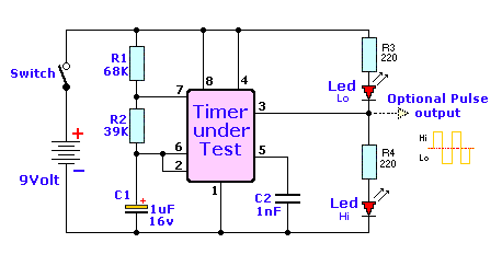
Timer multivibrator monostable lm555 astable stable unstable555 timer circuit circuits ic diagram testing supply power input ends 15v 1x2 1x1 terminals provided must between 555 timer chip tester.

.

How does NE555 timer circuit work | Datasheet | Pinout | ElecCircuit.com

Explain the functional block diagram of Timer IC555

Alternate Switching Relay Timer Circuit

555 Timer IC - Types, Construction, Working & Applications

Switching Two Alternate Loads ON/OFF with IC 555 - Homemade Circuit

Schematic 555 Timer Circuit Diagram / LM555 Electronics Schematic

11+ Optocoupler Tester Circuit Diagram | Robhosking Diagram

555 timer chip tester

555 Timer IC - Features, Pinout, Working, Circuit, Operating Modes

How does NE555 timer circuit work | Datasheet | Pinout | ElecCircuit.com